
Gyroscopic Instruments
Definition
Explanation
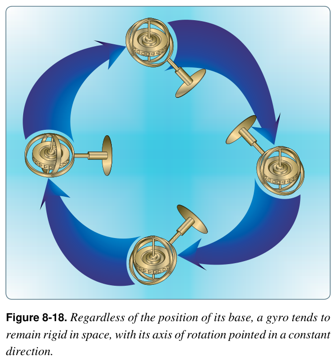
Rigidity is what the attitude and heading indicators use — the gyro stays put while the airplane turns and pitches around it. Precession is what the turn coordinator uses — a turn feeds a force into the gyro, and the gyro's 90-degrees-later reaction is what deflects the needle to show your rate. Understanding these two properties is the key to every gyro instrument and every gyro failure.
Why it matters
A DPE might ask
- What are the two properties of a gyroscope?
- Which instruments use rigidity, and which uses precession?
Definition
Explanation
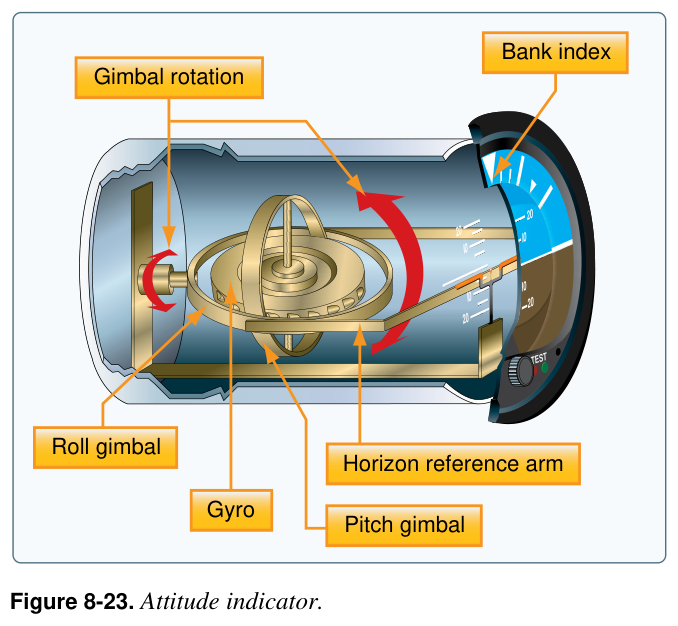
Read it like a window: blue is sky, brown is ground, and the miniature airplane's relationship to the horizon is your attitude. Bank is shown by the pointer against the scale at the top; pitch by the airplane above or below the horizon. Modern attitude indicators have small, well-corrected acceleration and turn errors you rarely notice.
Why it matters
A DPE might ask
- What does the attitude indicator show, and what powers it?
- What gyroscopic property does it use?
Definition
Explanation
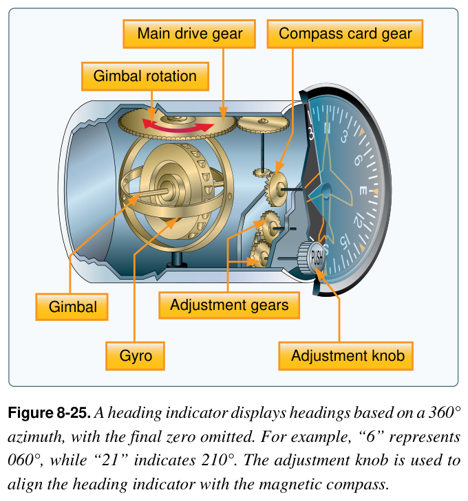
Reset the heading indicator to the magnetic compass about every 15 minutes, and only in straight-and-level, unaccelerated flight — that's when the compass reads true. Between resets you fly the steady gyro; you just don't trust it to stay perfect on its own. It's typically vacuum-driven, so a vacuum failure takes it down along with the attitude indicator.
Why it matters
A common mistake is trusting the heading indicator indefinitely, or resetting it in a turn. It drifts over time, and the compass only reads correctly when you're straight, level, and unaccelerated — so reset the gyro to the compass under those conditions, roughly every 15 minutes.
You should reset the heading indicator to the magnetic compass:
A DPE might ask
- Why and when do you reset the heading indicator?
- Why is the heading indicator steadier than the compass?
Definition
Explanation
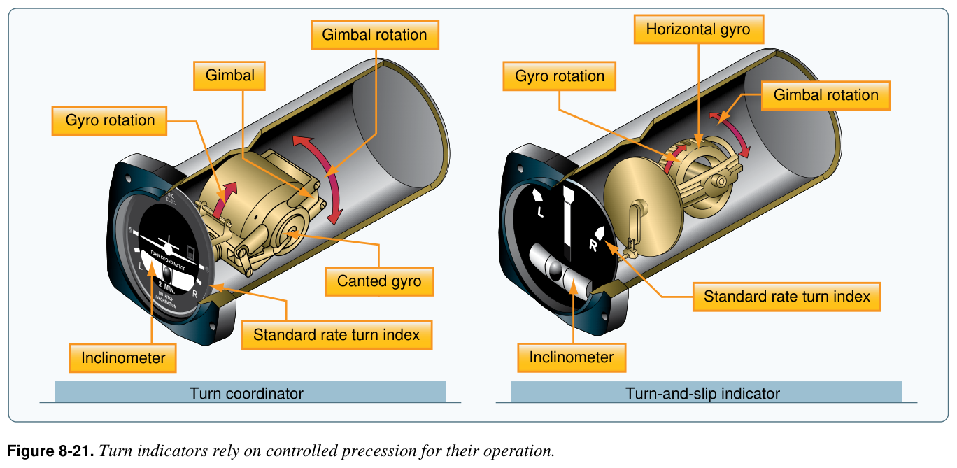
Two instruments in one. The airplane shows rate (how fast you're turning). The ball shows coordination (whether your rudder and bank are balanced): centered is coordinated; off to one side means you're slipping or skidding — 'step on the ball' (add rudder toward the side the ball is on) to center it. The turn coordinator is typically electric, so it keeps working if the vacuum system fails.
Why it matters
A DPE might ask
- What does the turn coordinator show, and what does the ball show?
- What is a standard-rate turn?
Definition
Explanation
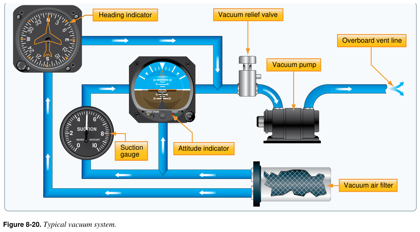
Catch it early: check the suction gauge (a low or zero reading means the pump), and cross-check your gyros against the others — if the attitude indicator disagrees with the turn coordinator, altimeter, and airspeed, suspect vacuum. Then fly partial panel: use the electric turn coordinator plus airspeed, altimeter, and the magnetic compass to keep control while you get to better conditions. The full partial-panel technique is the next lessons' focus.
Why it matters
The deadly mistake is trusting the attitude indicator as it slowly fails. A dying vacuum gyro doesn't snap to a flag — it drifts, so a wings-level airplane can show a subtle bank and lead you into a spiral. Cross-check: if the attitude indicator disagrees with the turn coordinator, ball, altimeter, and airspeed, believe the others and fly partial panel.
Your vacuum pump fails in flight. Which instruments are affected, and which do you fly?
A DPE might ask
- How are your gyros powered, and why split them?
- How would you recognize and handle a vacuum failure?
Definition
Explanation
It all comes back to how each gyro is powered and what property it uses: that tells you both its normal job and its failure mode. Reset the heading indicator, keep the ball centered, watch the suction gauge, and be ready to fly partial panel on the electric turn coordinator when the vacuum quits.
| Instrument | Principle · power · if vacuum fails |
|---|---|
| Attitude indicator | Rigidity · shows pitch & bank · usually vacuum — fails with the pump. |
| Heading indicator | Rigidity · stable heading, but drifts — reset to the compass ~every 15 min · usually vacuum — fails with the pump. |
| Turn coordinator | Precession · turn rate + the ball for coordination · usually electric — survives a vacuum failure. |
| Vacuum failure Watch | Insidious — attitude & heading spin down slowly. Check the suction gauge, cross-check, fly partial panel. |
Why it matters
A DPE might ask
- Summarize the principle, power, and failure of each gyro instrument.
- What survives a vacuum failure, and how do you fly it?